Compressor Surge Test Rig
The safe operating range of pressure and mass flow for centrifugal compressors is limited by a dynamic flow instability known as surge. Surge occurs as the mass flow through the compressor is reduced to a critical point where the flow pattern becomes unstable. This critical point, called the surge point, separates the stable and unstable operating region of the compressor in the compressor characteristic curve. Surge causes large-amplitude low-frequency oscillations of pressure ratio and mass flow rate in compression systems and even flow reversal, putting a high load on the compressor impeller and casing. This causes undesired vibration, high temperature, compressor damage and lost productivity.
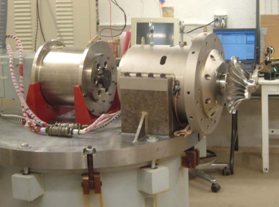
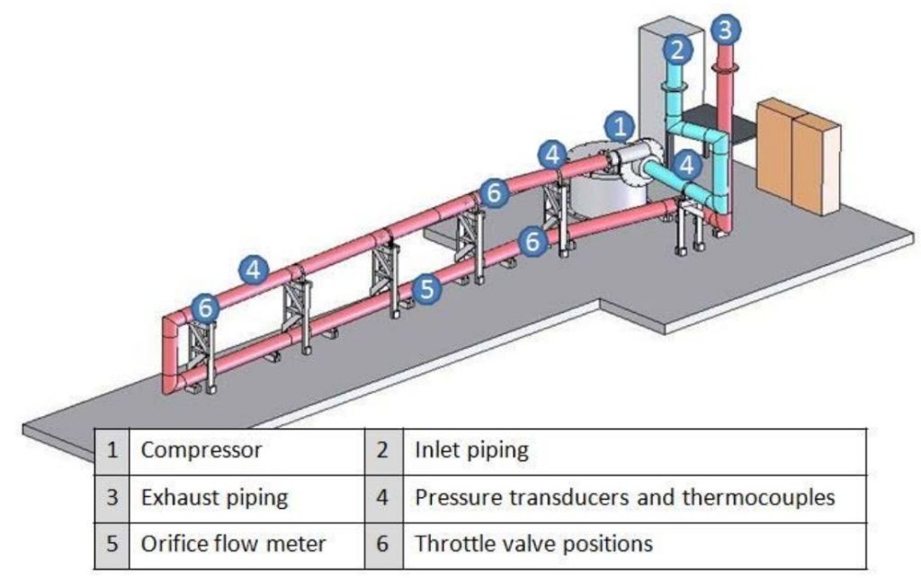
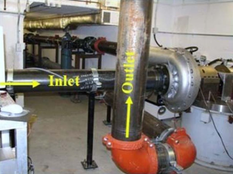
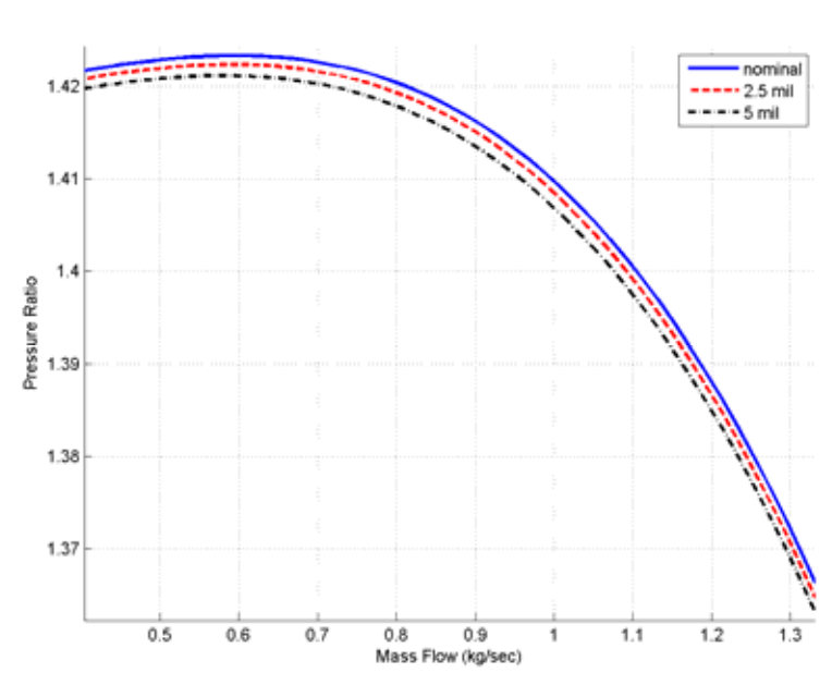
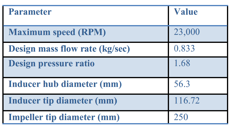
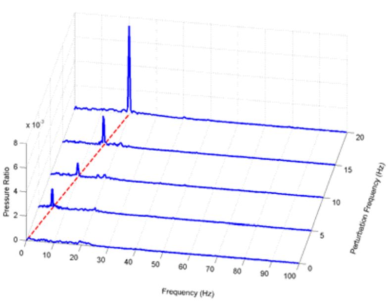
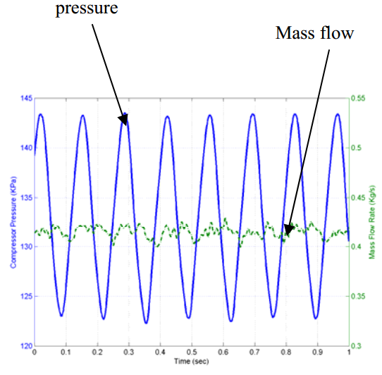
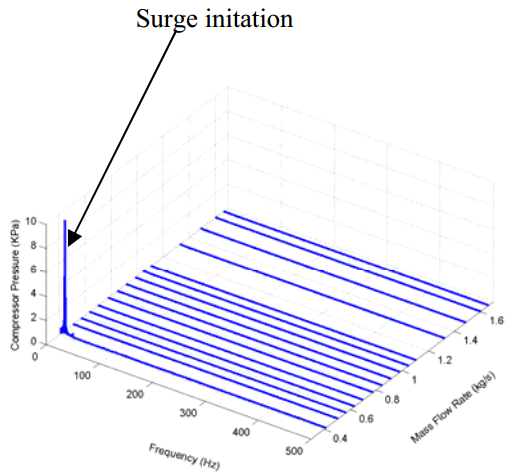
For the experimental study of compressor surge, the Compressor Surge Test Rig was commissioned by ROMAC. The test rig is a single-stage overhung centrifugal compressor, and the rotor is levitated on two radial active magnetic bearings (AMBs) that allow it to rotate freely without any mechanical contact. The rotor is axially supported by a thrust AMB, which also gives the flexibility to control the impeller tip clearance with high precision. The unshrouded impeller and volute of the compressor was manufactured and provided by Kobelco for this test rig. It operates with a vaneless diffuser. A modular ducting system at the compressor exhaust forms the variable plenum volume for the compression system, where the position of a throttle valve can be moved along the piping in order to change its volume. The Table summarizes the design and performance parameters of the centrifugal compressor. The objective of the Compressor Surge Test Rig is to develop an innovative active surge controller by taking advantage of the versatility of magnetic bearings. The general concept is to use the tip clearance variation to generate a pressure wave travelling towards the flow control valve to “cancel” the pressure wave generated by the initiation of surge. With measured flow information from pressure and flow rate sensors along the compressor, the proposed surge control algorithm calculates, at real time, the required impeller tip clearance variation to stabilize the compressor in the presence of surge, which is fed to the thrust AMB controller as the commanded impeller position. Assembly of the compressor was completed in 2008 and the test rig was commissioned. We are currently testing the compressor performance at different operating conditions in order to correlate the experimental setup to our mathematical model. One of the most important components of our model is the relationship between the compressor pressure ratio and impeller tip clearance. The diagram below shows the results of the static clearance test, where we mapped the compressor characteristic curve at nominal and increased impeller tip clearance. It can be seen that as the clearance between the impeller and the shroud increases, the increased tip leakage lowers the compressor efficiency and pushes the compressor characteristic curve down. The waterfall plot shows the frequency components for the compressor exhaust pressure ratio signal when the impeller was axially modulated at various input perturbation frequency. We can find in figure a predominant frequency component matching the frequency of the perturbation signal, which shows that the tip clearance has a dynamic effect on the compressor pressure ratio. Further work is needed to experimentally identify the transfer function of the system from impeller clearance to compressor pressure ratio, and fully validate its dynamic characteristics by comparing it to theoretical predictions. The dynamics of the compression system was tested in the surge condition, where the mass flow through the compression system was kept below the surge point by closing the throttle valve. The pressure ratio diagram shows pressure and mass flow rate measurement during surge, and a very dominant oscillation of about 7Hz characterizes both measurements. This frequency matches the frequency generally found in deep surge, and agrees with the frequency predicted by the mathematical model. The effect of surge on the compressor states can be seen clearly in the waterfall plot of the frequency components of compressor pressure ratio at different mass flow rates. We can see in the figure that, at flows rates below 0.5kg/sec, a dominant component appears suddenly at 7Hz, which matches the expected frequency of the surge oscillation. After completing the tasks required to match the mathematical model of the compressor to our experimental setup, we plan to start the implementation of the surge controller. With the collected experimental data of the compressor characteristics, we will update the compressor model and surge control algorithm. We are continuing our effort to derive a robust surge controller that stabilizes the compressor system beyond the stable operating range. The derived controller will be implemented in our test rig, and its effectiveness to mitigate compressor surge will be tested.
Contact:
University of Virginia
ROMAC Rotating Machinery and Controls Laboratory